
Pegnitz tunnel
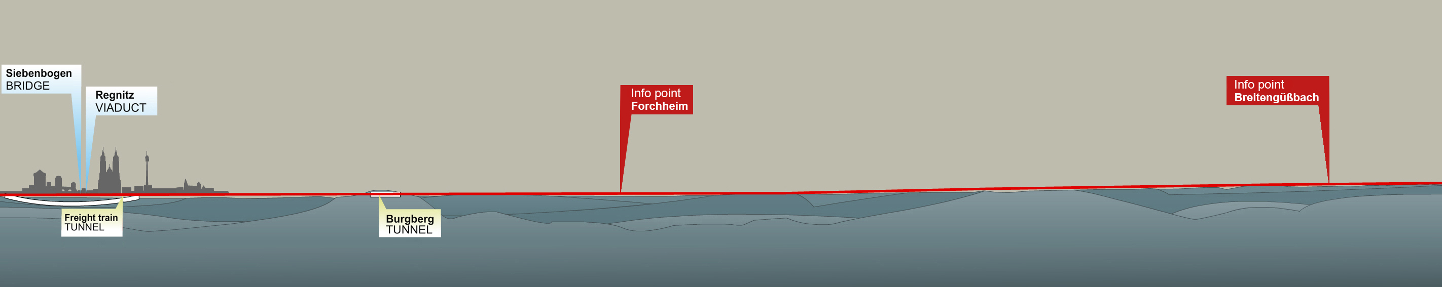
Most of freight line 5955 consists of a tunnel – the Pegnitz tunnel, which itself consists of five sections. There is an entry section at the north and south in the form of a trough. The troughs are followed by a cut-and-cover section. In the centre is a section of tunnel constructed by the mining method. The emergency exits and the technical equipment also form part of the tunnel.
In the early 1990s, the original plan provided for the tunnel to be driven using the new Austrian tunnelling method (NATM). However, tunnel driving technology using a tunnel boring machine (TBM) has moved on so far in the last 15 years that it is now possible to drive such large cross-sections with a machine. This formed the point of departure for the plans updated in 2009.
Fact and Figures
| Overall length: | 7.500 m |
| Cut-and-cover method: | |
| Clearance: | 10,40 m |
| Clear width: | 6,69 m |
| Enclosed construction method: | |
| Clearance: | 7,66 m |
| Clear width: | 10,64 m |
| Tunnel tube diameters: | 11,64 |
| Maximum longitudinal gradient: | 12,5 ‰ |
| Maximum overburden: | 25 m |
| Tubbing thickness: | 0,50m |
| Spoil: | 750.000 m3 |
| Emergency exits: | 14 |
| Construction method: | Cut-and-cover method + tunnelling |
| Tracks: | 2 |
| Permanent way: | Solidtrack |
| Design speed: | Vmax 120 km/h |
| Line commissioning date: | 2021 |
The railway tunnel
The Pegnitz tunnel was conceived as a tunnel with a cross-section large enough for twin railway tracks with the standard loading gauge from the outset. Nothing has changed since. Its position in urban areas of Fürth and Nuremberg does not allow the construction of twin single-track bores, for geometrical reasons. There are no areas which provide sufficient space for ramps to two bores while still allowing sufficient clearance for construction, so the concept of one double-track bore was retained. The cross-section had to be sufficiently large.
The tunnel has two peculiarities. Firstly, it will be for freight only. No passenger trains are intended to pass through it. Secondly,. it is a tub tunnel, in which there is a low point between the two portals, so that trains first have to descend a gradient, then ascend again. The tracks require a transitional section for this purpose, as railway tunnels cannot simply have entrances and exits with any gradient. The maximum longitudinal gradient of the tunnel is restricted to 1.25%. This is the usual limit for longitudinal gradients for rail freight. Gentler gradients are planned wherever possible.

The troughs
Ramps lying in reinforced concrete troughs will be required at the tunnel entrance and exit. They will link the tunnel with the surface. At the southern end, the trough will be at the precise point where the existing line from Fürth to the marshalling yard is located. The tracks will be moved apart, as shown in the graphic above, and the trough sited between them. The Rothenburger Strasse bridge has already been constructed to allow for this. In the north, the trough commences where the new rapid transit trackbed is crossed, right alongside the A73 motorway, ending just before the Stadeln –– Steinach link load, where the line is already on an embankment.


Boring
The Pegnitz tunnel will be driven by a TBM from the north, immediately to the north of the Reichgraben road in Fürth. A hydro-shield machine, operated by specialists and built for this project, will be used for driving, due to the urban location of the freight train tunnel and the predominating soil and groundwater conditions.
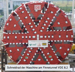
The cutter head, specially designed for the ground to be traversed, bores slowly into the rock under pressure, creating a circular cavity with an external diameter of approximately 13 m. The fabric of the tunnel bore is completed immediately by a protective steel tube, the shield, containing prefabricated concrete segments (tubbing)

This creates a single homogeneous tunnel lining, which secures the cavity and provides the necessary waterproof seal. A rail system usually supplies the tunnel with tubbing and material.
 The hydro-shield method to be used here represents an operationally safe, environmentally-friendly process, characterised by low settlement and a minimal effect on groundwater.
The hydro-shield method involves fluid-supported tunnel driving in which the excavation chamber is filled with a slurry, consisting of bentonite (clay) and water, which supports the excavated cavity and seals it against water. The pressure of the supporting medium is regulated so that it is in equilibrium with the existing external loads imposed by ground and water pressure. The spoil is pumped through pipes out of the tunnel into a separator on the surface, in which the slurry is separated from the spoil and then returned to the suspension circuit.
Once the TBM has passed Nuremberg-Grossmarkt it will be dismantled in the reception pit and removed.

The cut-and-cover method
The bored tunnel will be followed by cut-and-cover sections to the north and south. They will have a rectangular reinforced concrete cross-section and be built in an open trench. Otherwise, they will be configured analogously to the circular cross-section. In the north, the cut-and-cover section will begin on the main construction site set-up area to the immediate north of the Reichgraben bridge. In the south, the cut-and-cover section will be to the south of Zuckermandelweg, alongside the sports ground.